


-


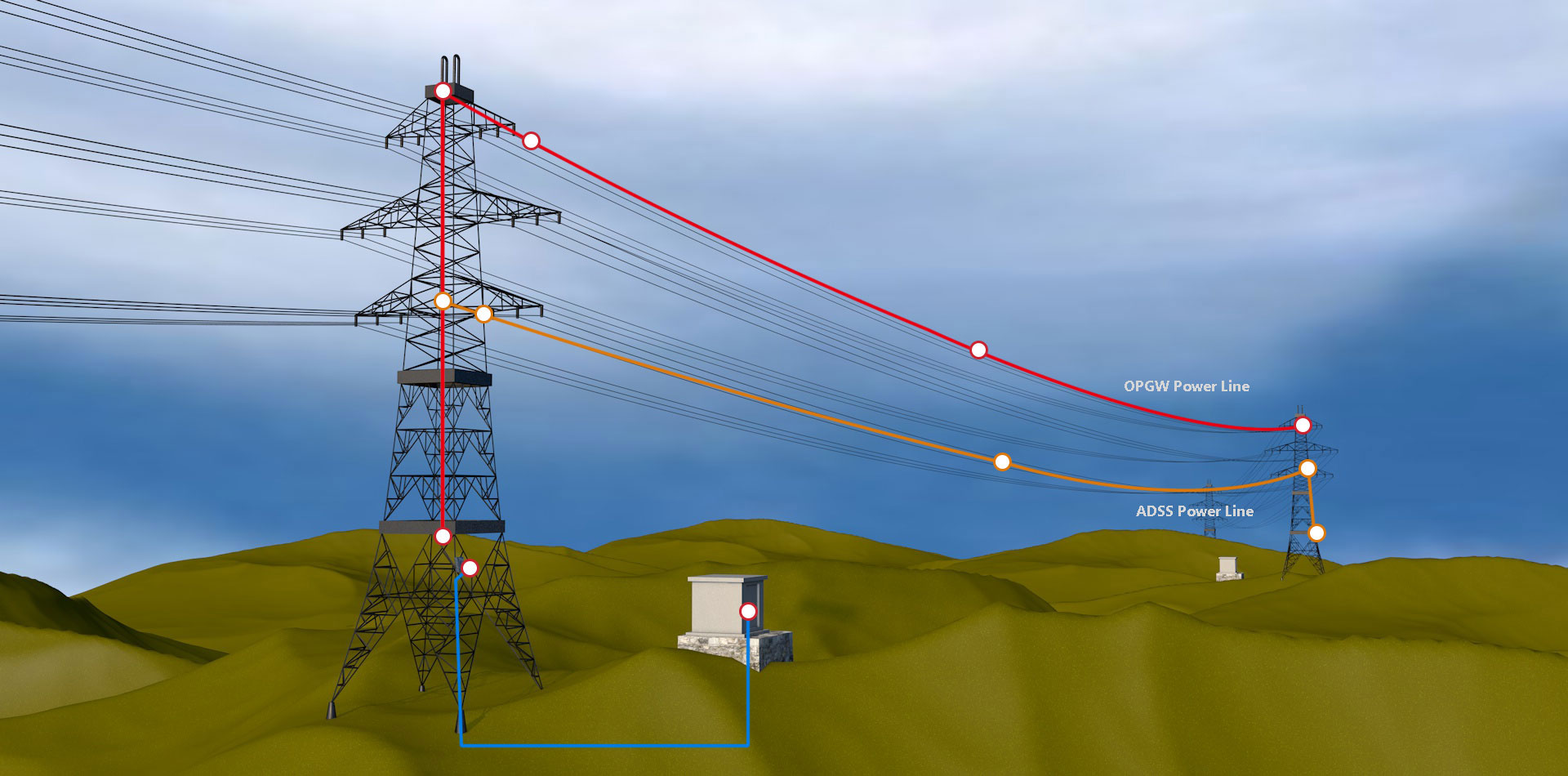
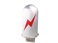
ADSS Fiber Optic Cable
Single & Doube Jackets ADSS Cable; Excellent AT performance. The maximum inductive at the operating point Of AT jacket can reach 25kV
-


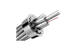
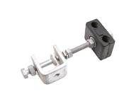
OPGW Fiber Optic Cable
KSD provide years of experience and excellent solutions for your hardware needs in OPGW (Optical Ground Wire) cables.
-


FTTH Drop Cable
GJXFH/ GJYXFCH/ GJYXFCH/ STEEL STEEL STRAND GJYXFFCH/ GJXFH/ GJYXFCH(V) STEEL/ GYXTC8KH
-


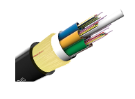
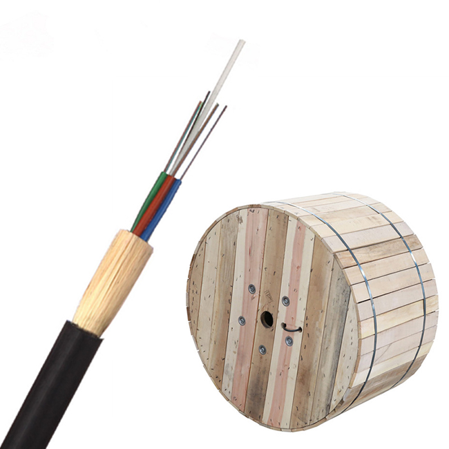
Outdoor Fiber Optic Cable
Aerial/ Direct-buried/ Duct Fiber Optic Cables;ADSS / OPGW/ GYTA / GYFTY GYTA53 / GYXTW /FTTH / GYTS
-


Indoor Fiber Optic Cable
Single mode indoor fiber optic cable OM2 multi-mode indoor fiber optic cable OM3 multi-mode indoor fiber optic cable
-


Air Blown Fiber Optic Cable
-Small diameter -Long blowing distance -Excellent Structure